- Eng
- Deu
- Fra
Why Choose a Vane Pump for Industrial Applications?
Industrial equipment is demanding more controlled, efficient fluid power. MarketsandMarkets reports that the global hydraulic pumps market is projected to grow steadily through 2028, driven by manufacturing, construction, and mobile machinery. This growth raises a practical question: why choose a vane pump for industrial applications?
A vane pump uses sliding vanes inside a rotating cartridge to move fluid smoothly. Its balanced design can reduce pulsation, vibration, and operating noise. That matters beside workers, sensors, and precision valves. In a factory, a well-selected vane pump can support hydraulic presses, injection-molding systems, lubrication units, and material-handling equipment. It can also provide reliable flow across changing operating conditions, especially when the system needs moderate pressure and consistent delivery.
The U.S. Department of Energy identifies pumping systems as significant industrial energy users, making efficiency and maintenance important lifecycle concerns. Vane pumps can contribute through efficient volumetric performance, compact construction, and relatively simple service procedures. However, performance depends on fluid cleanliness, temperature, speed, and correct inlet conditions. This is where many purchasing decisions become less comfortable.
No pump is universally best.
ISO 4413 emphasizes safe hydraulic-system design, including pressure control, contamination management, and maintenance provisions. Engineers should therefore compare vane pumps with gear and piston alternatives using measured duty cycles, not brochure claims alone. A poorly sized vane pump may suffer wear, leakage, or premature failure. That caveat matters. The strongest choice combines manufacturer testing, application experience, filtration data, and total cost analysis. Reports show market momentum, but real equipment still decides the result.
Vane Pump Fundamentals and Operating Principles
Why Choose a Vane Pump for Industrial Applications?
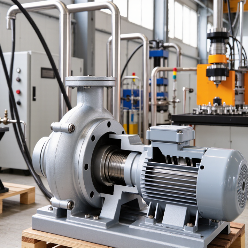
A vane pump uses a rotor mounted slightly off-center inside a sealed housing. Sliding vanes sit in rotor slots and follow the housing’s inner surface. As the rotor turns, inlet chambers expand and draw in fluid. Outlet chambers shrink and deliver pressurized fluid. Simple geometry matters. This action produces a relatively steady flow with limited pulsation. It also supports compact designs and quieter operation than many other positive-displacement pumps.
Vane pumps suit machine tools, material-handling equipment, and industrial power units requiring moderate pressure and consistent delivery. Their performance depends heavily on fluid cleanliness, viscosity, and vane contact. Fine particles can score the housing and reduce volumetric efficiency. In field maintenance, checking filters and monitoring unusual noise often prevents expensive downtime. The U.S. Department of Energy reports that pumping systems can consume 25–50% of energy in some industrial facilities. Correct displacement, pressure control, and motor sizing therefore deserve careful attention.
The principle looks simple, but selection is not. A pump can meet the pressure rating and still perform poorly with cold oil or frequent starts. ISO 4413 guidance emphasizes contamination control, safe pressure limitation, and proper system design for hydraulic equipment. A relief valve remains essential. So does honest testing under real load. Vane pumps are not universal solutions; severe contamination or extreme pressure may expose their weaknesses. That uncomfortable detail is easy to overlook during specification.
Why Choose a Vane Pump for Industrial Applications? - Vane Pump Fundamentals and Operating Principles
| Design or Operating Dimension | Typical Data or Characteristic | Industrial Relevance | Engineering Consideration |
|---|---|---|---|
| Basic Operating Principle | A rotor carries sliding vanes inside a cam ring or elliptical housing. The changing chamber volume draws in and discharges fluid. | Provides continuous positive-displacement flow for hydraulic power units, lubrication systems, and process equipment. | Flow is primarily determined by displacement and rotational speed, while system pressure is controlled by downstream resistance and relief protection. |
| Pump Type | Positive-displacement rotary pump | Suitable for applications requiring a predictable flow rate at low, medium, or moderately high pressure. | A relief valve or other pressure-limiting device is required because a positive-displacement pump continues to generate flow when the outlet is restricted. |
| Common Displacement Range | Approximately 5–250 cm³/rev for many industrial hydraulic vane pumps | Supports compact auxiliary circuits as well as larger machine-tool, material-handling, and industrial power systems. | The actual range varies considerably by construction, shaft size, operating speed, and pressure rating. |
| Typical Flow Range | Approximately 5–300 L/min in industrial hydraulic installations | Can supply steady flow to actuators, control valves, lubrication circuits, and cooling or filtration systems. | Theoretical flow can be estimated as displacement multiplied by speed; volumetric efficiency reduces delivered flow under load. |
| Typical Pressure Capability | Common industrial ranges are about 70–210 bar; specialized designs may reach higher ratings. | Appropriate for many hydraulic circuits that do not require the highest pressure levels available from some piston pumps. | Pressure capability depends on vane loading, housing design, fluid viscosity, speed, temperature, and the manufacturer’s rating for the specific pump. |
| Speed Range | Often approximately 600–3,000 rpm, depending on pump size and fluid conditions | Allows direct coupling to common electric motors and engine-driven systems. | Minimum speed must maintain adequate lubrication and vane extension; excessive speed can increase noise, wear, and inlet losses. |
| Flow Smoothness | Generally smooth and low-pulsation flow compared with many other positive-displacement pump arrangements | Useful for proportional control, machine tools, servo-assisted equipment, and systems sensitive to flow variation. | Pulsation is affected by vane count, port geometry, speed, internal clearances, and fluid compressibility. |
| Noise Performance | Typically low to moderate noise when correctly sized and operated within the recommended inlet conditions | Beneficial in indoor factories, automation cells, test equipment, and operator-controlled machinery. | Aeration, cavitation, misalignment, worn components, excessive speed, and restrictive suction piping can significantly increase noise. |
| Volumetric Efficiency | Commonly about 80–95% at rated operating conditions | Supports efficient conversion of motor speed into useful hydraulic flow. | Efficiency decreases as internal leakage increases with pressure, temperature, wear, or unsuitable fluid viscosity. |
| Mechanical Efficiency | Often approximately 85–95%, depending on design and operating point | Helps limit the drive motor size and operating energy required for a specified hydraulic output. | Friction from vane tips, bearings, seals, and excessive pressure can reduce mechanical efficiency. |
| Fluid Compatibility | Commonly used with mineral-based hydraulic oils; selected synthetic or biodegradable fluids may also be suitable. | Fits a broad range of hydraulic, lubrication, and industrial fluid-power systems. | Fluid compatibility must be confirmed for vane material, seals, temperature range, viscosity, additives, and contamination level. |
| Viscosity Requirement | Many hydraulic applications operate near 15–400 mm²/s, with a narrower optimum range at normal temperature. | Allows operation across varying ambient and fluid temperatures when the correct grade and cooling method are selected. | Low viscosity can increase leakage and wear; high viscosity can cause poor filling, high starting torque, and cavitation risk. |
| Self-Priming Capability | Generally self-priming when the pump is correctly installed and the inlet line is properly filled. | Simplifies startup in many tank-mounted and flooded-inlet hydraulic systems. | Self-priming ability is not unlimited; dry running, excessive suction lift, air leaks, and inadequate inlet conditions can damage the pump. |
| Contamination Sensitivity | Moderate to high, because vane tips and internal clearances require clean fluid. | Reliable operation is achievable in industrial systems with suitable filtration and contamination control. | Use correctly sized inlet and return filtration, maintain clean assembly practices, and monitor fluid condition. |
| Maintenance Requirements | Periodic inspection of fluid condition, filters, shaft seals, bearings, rotor, vanes, and cam ring | Predictive maintenance can reduce unplanned downtime and preserve flow and pressure performance. | Common warning signs include reduced flow, rising case temperature, abnormal noise, leakage, and increased power consumption. |
| Primary Advantages | Smooth flow, relatively low noise, compact packaging, good efficiency, and straightforward maintenance | Well suited to industrial machinery, hydraulic power units, injection equipment, presses, and lubrication systems. | The best results occur when the pump is matched to the required pressure, flow, speed, fluid, and duty cycle. |
| Primary Limitations | More sensitive to contamination and dry running than some simple gear-pump arrangements; pressure capability is often below that of high-pressure piston pumps. | May be less suitable for extremely high-pressure systems, heavily contaminated fluids, or applications with frequent dry starts. | Application screening should include pressure peaks, inlet conditions, temperature, fluid cleanliness, duty cycle, and required service life. |
| Best-Fit Applications | Hydraulic power units, machine tools, presses, material handling, industrial automation, lubrication, and fluid transfer | Offers a balanced combination of flow stability, operating noise, efficiency, and installation flexibility. | Selection should be based on calculated demand rather than nominal flow alone, including peak load and thermal requirements. |
Note: The numerical values are general engineering ranges for industrial vane-pump systems. Actual performance depends on pump construction, fluid properties, operating temperature, speed, pressure, installation quality, and the specific duty cycle.
Related Posts
-
Top Vane Pump Types for Efficient Fluid Management Solutions?
-

Why Choose a Rotary Pump for Your Industrial Applications?
-
How to Choose the Best Rotary Pump for Your Needs?
-

Top Vane Pump Options for Global Buyers in 2026?
-

What are the Benefits of Using Rotary Pumps in Various Industries?
-

Top Vacuum Pump Suppliers in China for Global Buyers?